
Building the Death Star Laser Tower Model
Like many people, Star Wars: A New Hope was a seminal film for me. It came out during my freshman year in college and immediately changed the direction of my education and career. From that moment on I wanted to build models for the movies. While I have built models for many movies and televisions shows over the years I never got the opportunity to work for a Star Wars film. But now I can do the next best thing, build them for fun!
For this project I'll be making a studio scale replica of one of the Laser Towers from the Death Star seen during the final battle in the film.
PART ONE: SOURCING REFERENCE AND 3D DESIGN
"Reverse Engineering" is a term used to describe the process of figuring out the size and shape of something using photographs. This can be done in 2D or 3D, although reverse engineering in 3D requires some pretty sophisticated software and detailed information about the photos must be known such as the focal length of the lens, exposure aperture and distance to subject. 2D reverse engineering is basically digital tracing over a photo and then determining its size using landmarks of known size and/or some educated guessing!
Fortunately there are a wealth of photos of the original Laser Tower model on the web. The original filming model was on public display a few years back part of the touring Star Wars Exhibition and several fans shot extensive photos of it and posted them online for the benefit of fellow modelmakers. There are also some nice still images of the model in the Special Features section of the Blu-Ray disc of the movie.

The trick to successful reverse engineering is to start with a photo shot square on to the model with as little perspective in it as possible. Most digital drawing and modeling programs will allow a photo to be imported and drawn over. For modeling projects like this one my software of choice is Rhino 3D, which allows me to import photos and create 2D drawings, as well as 3D models which can be used for 3D printing, laser cutting and CNC routing, but more on that later.
Once I had drawn the basic outline of the turret and some key details over the photograph it was time to establish the actual size for the model. Sometimes the actual dimensions or scale of a model is known, or even better, it was possible to place a ruler next to the model during photography from which the size can be determined. Neither of those were a possibility in this case. However the laser barrels on the model were actually the engines from a known plastic model kit, a Revell 1/32 scale Mig 21, and I was able to purchase one of these kits on EBay. This would prove valuable both later on as a "donor part" for the model but also now as a way of determining the size of the turret by scaling the photograph and the drawn outlines to match the measured size of the kit part.
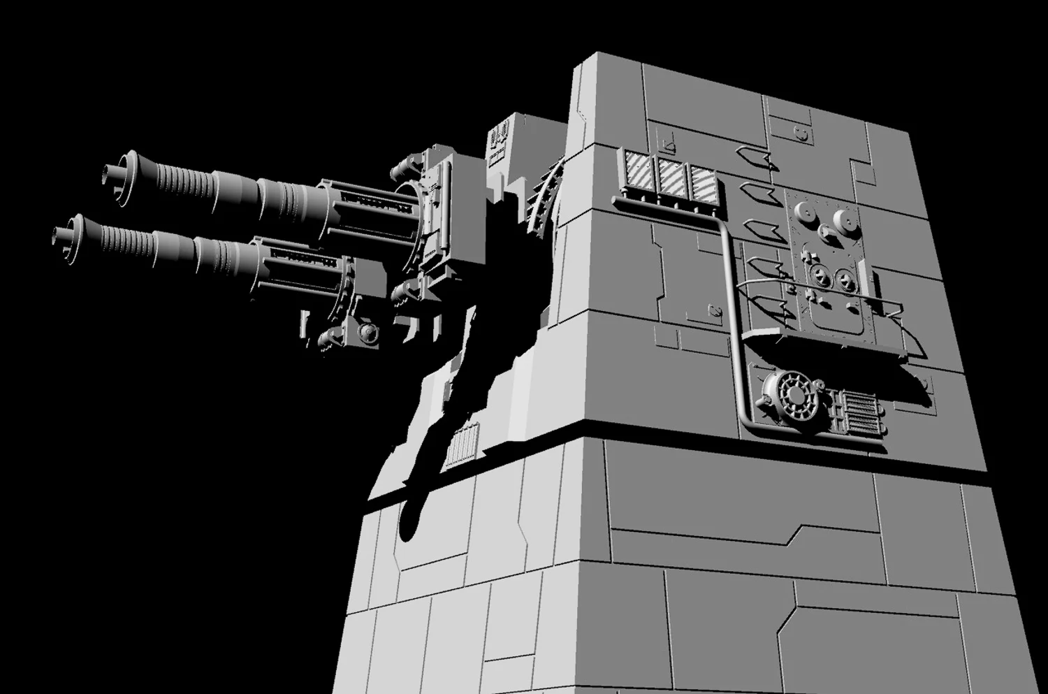
Using the 2D over-drawing as a guide, as well as other photographs, I proceeded to 3D model the Laser tower in Rhino 3D. This involved careful examination of the various reference photos from different angles as well as some educated guesses as to what areas might look like that could not be seen clearly. Over time a pretty comprehensive 3D model emerged.
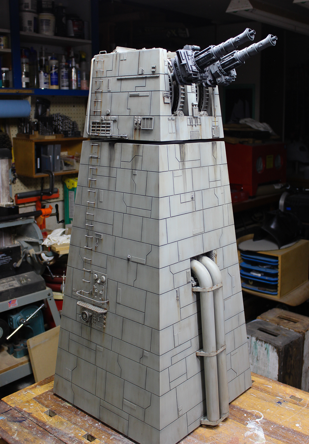
For the film, only the turret and a short section of the tower below it were actually built, as those were all that were necessary for the planned shots. I wanted my tower to be a little more imposing, so I extended the bottom of the tower to almost double the height of the model to 3 feet. This also allowed me to have fun making up some additional details lower on the tower not seen on the original filming model.
One of the great powers with using 3D modeling software in the design of physical models is that it allows you to not only work out the design but methods of fabrication as well. I broke up the solid mass of the tower into the various pieces from which it would be assembled. This "virtual model kit" allowed me to fine tune the construction long before starting the physical build. A digital form of "measure twice, cut once!"


From the 3D model of these individual parts accurate line drawings could be extracted. These drawings were then exported as .dxf files for use in CNC routing.
PART TWO: FABRICATING THE CASEWORK AND LASER CANONS
While the some of the materials and construction methods used to build the original Death Star Laser Tower filming model are not known, it was most likely made of a core structure of either wood or Plexiglas covered with panels cut from styrene sheet. The original model also had a mechanical armature and motors inside it that would rotate the turret and move the barrels to simulate firing at the Rebel X-Wing fighters. I'm building a static, non-moving display model so an interior mechanism won't be needed. (At least for now. I've designed the casework in such a way that I can put a mechanism into it a later time if desired.)
I'm going to fabricate the model using a more high tech approach than was available to the modelmakers at ILM in the 70's. Rather than hand cut styrene panels to clad the core structure, I'm going to use a CNC (Computer Numerically Controlled) router to both cut out the structural components as well as cut panels lines into the surface using the .dxf drawing files exported from the 3D computer model.
The material from which I'll cut the casework is a special premium MDF (Medium Density Fiberboard) ¼ inch thick made by Plum Creek. This material is similar to the fiberboard found at most home center and lumber stores except that it has a smoother surface and a denser, more consistent core. It's used mostly for making paint grade cabinets and signage and paints beautifully, even the cut edges.
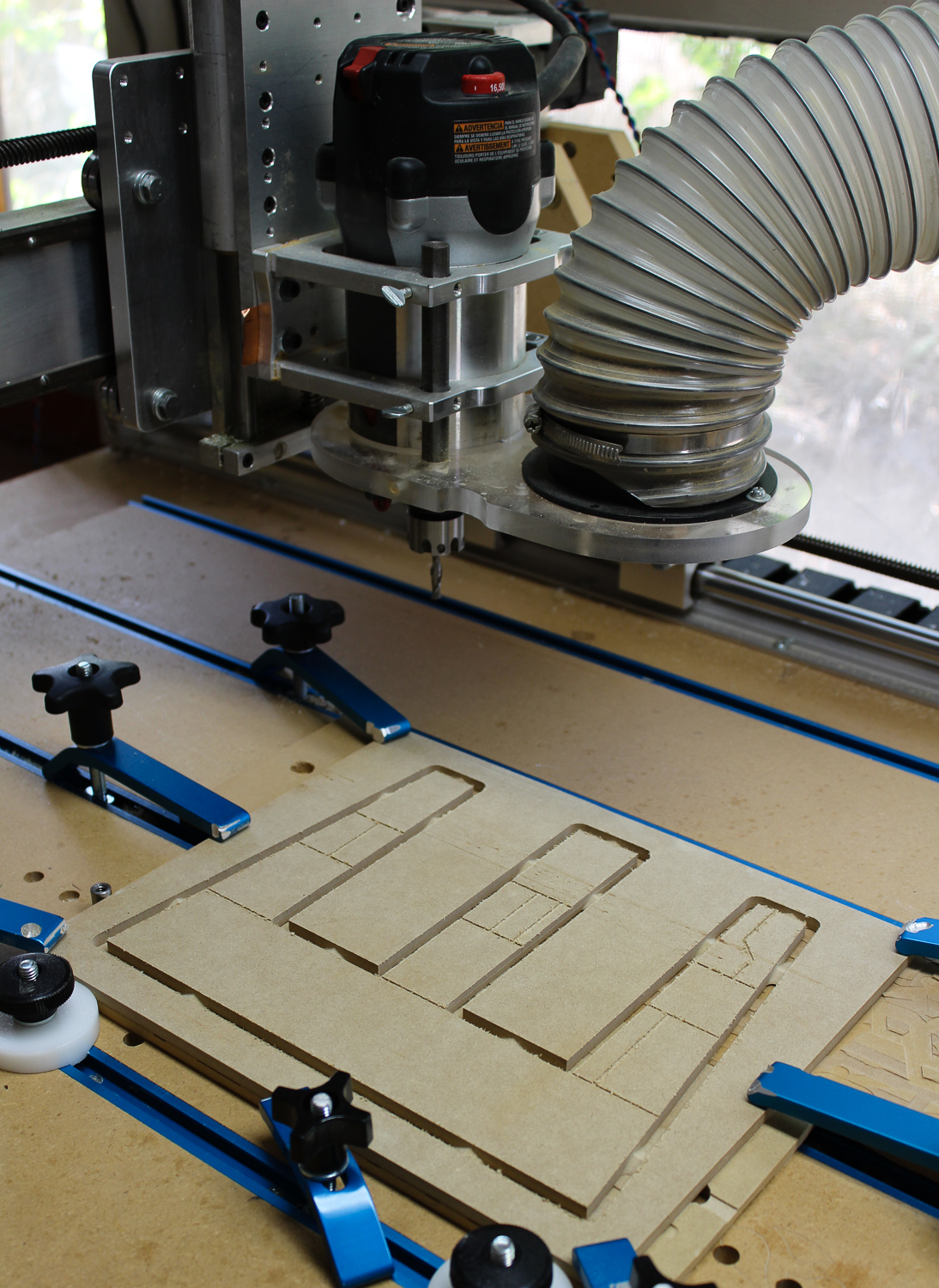
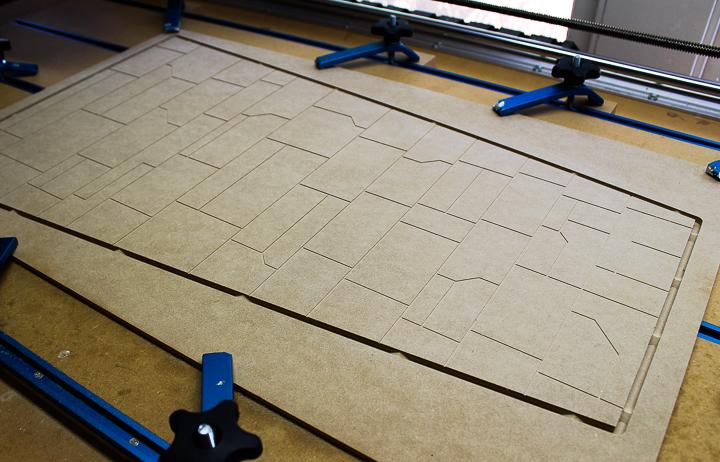
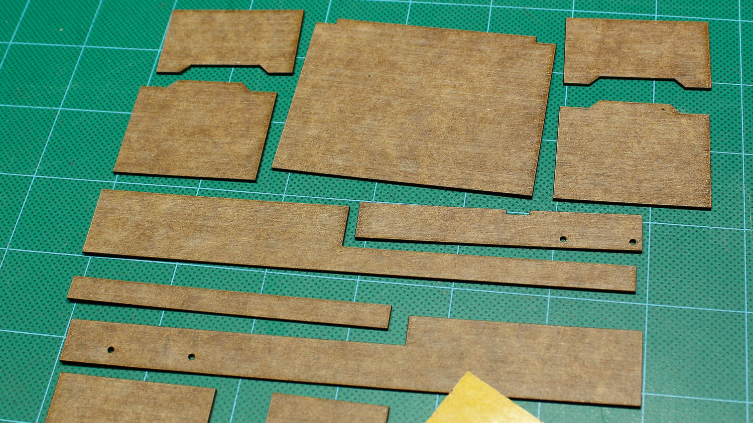
The .dxf files were loaded into the computer that controls the CNC router. I use a software program called V Carve from Vectric. The .dxf files are imported into the program where the various cutting depths, speeds and bit sizes are determined. V Carve calculates and exports the "G-Code" which is a standard machine language used to control CNC machine. The G Code is then imported into a program called Mach 3 that actually sends the control signals to the stepper motors that drive the router. The parts were then cut out of the MDF sheet material with a ¼ inch diameter router bit and the panels lines routed into the surface with a 1/16 inch diameter bit.
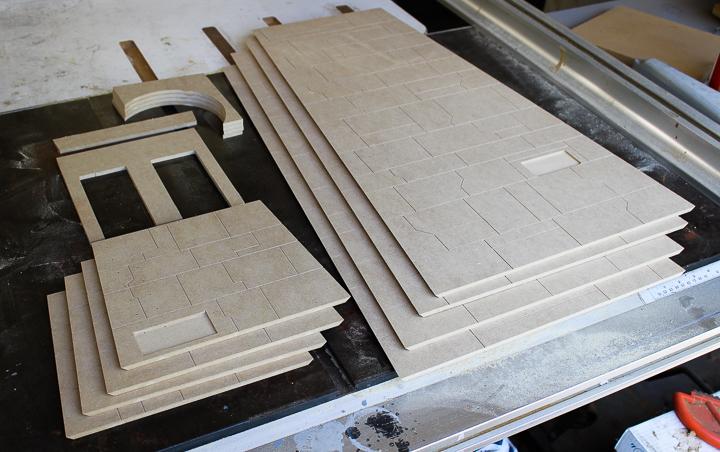
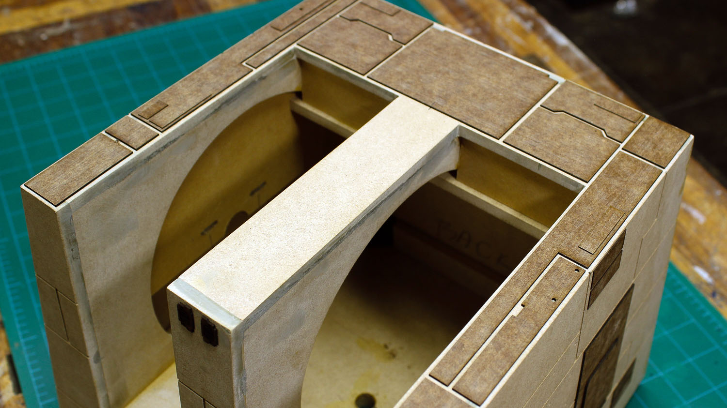
After being cut out on the CNC, the outer corners of the sides were mitered to a 45-degree angle on the table saw. In the end I had a stack of parts, my own kit, ready to assemble! MDF is a wood product and can be glued together easily with carpenters glue. The precision of the computer cut parts ensured that everything went together cleanly and accurately.
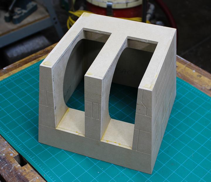

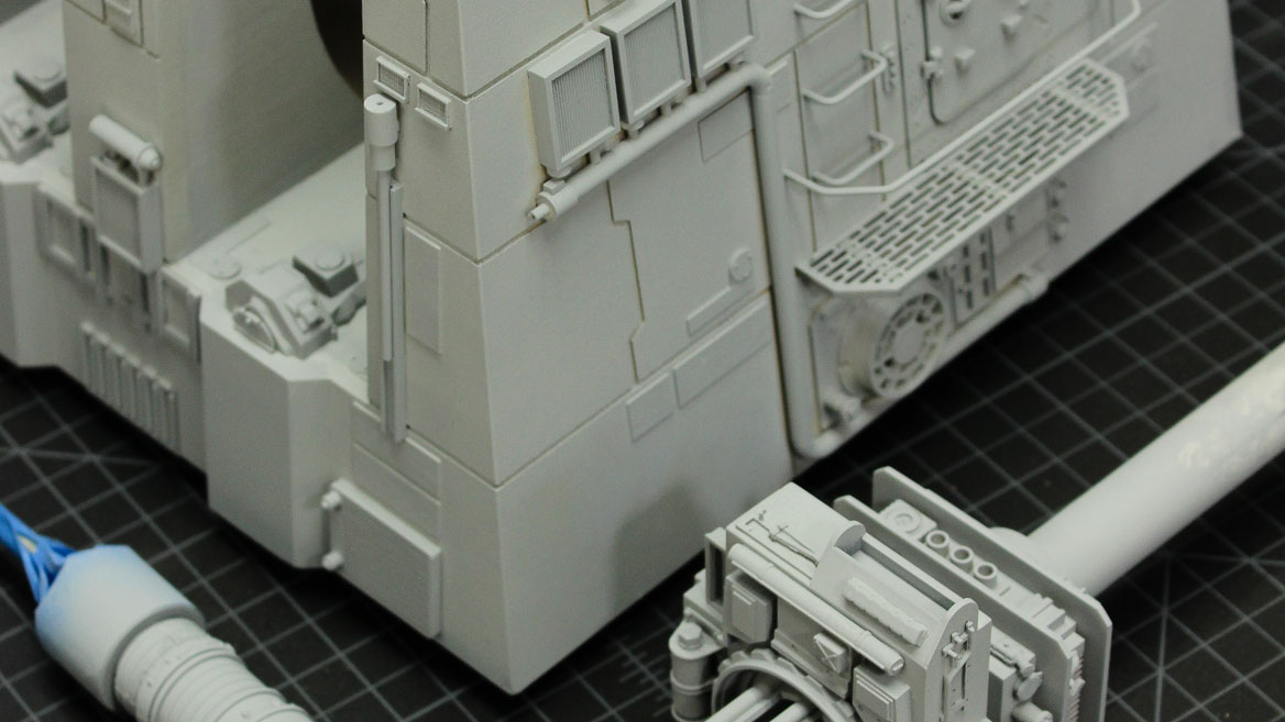
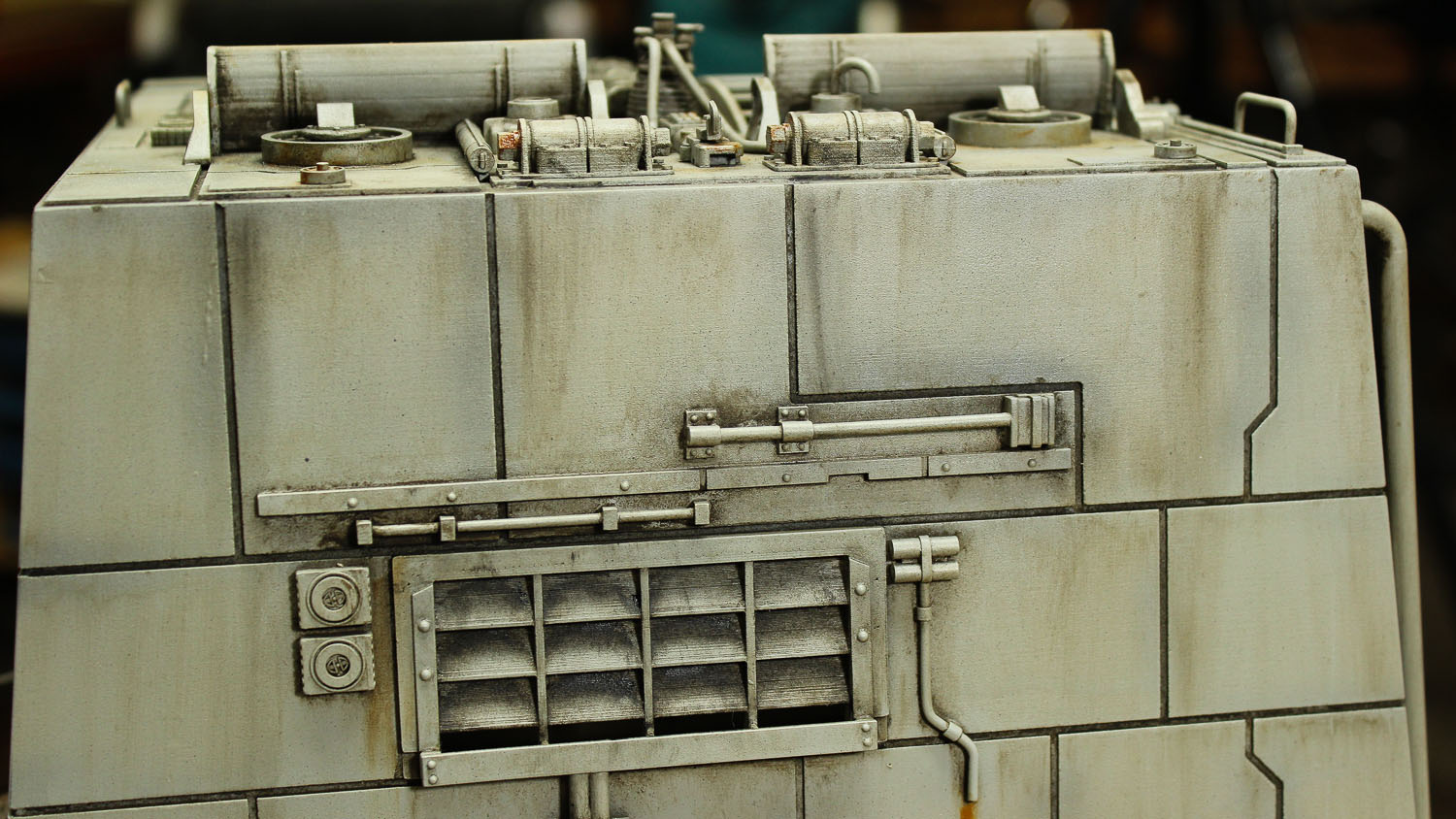
The assembled casework for the tower is of a really impressive size! Man this sucker is big! And the CNC routed panel lines are really clean and sharp.
With the structural casework of the Tower finished it was time to turn my attention to the details.
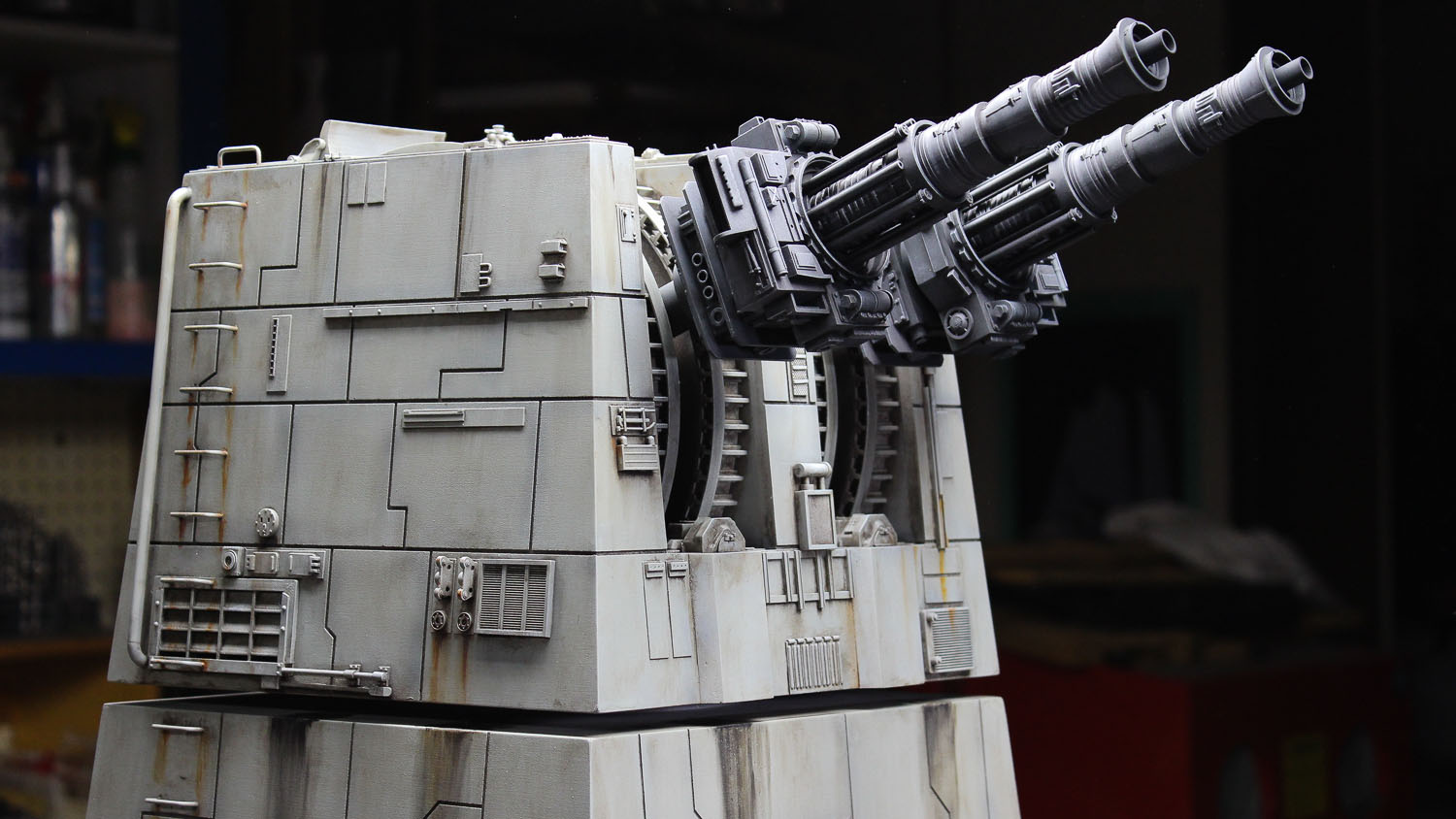
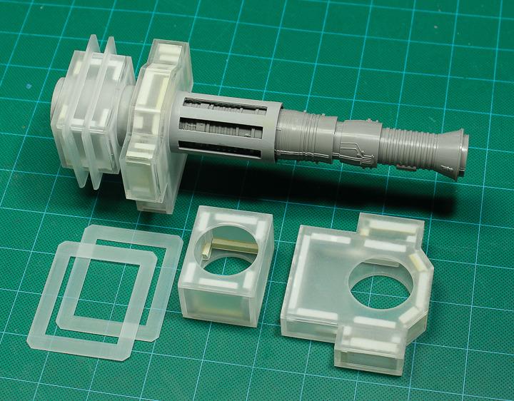
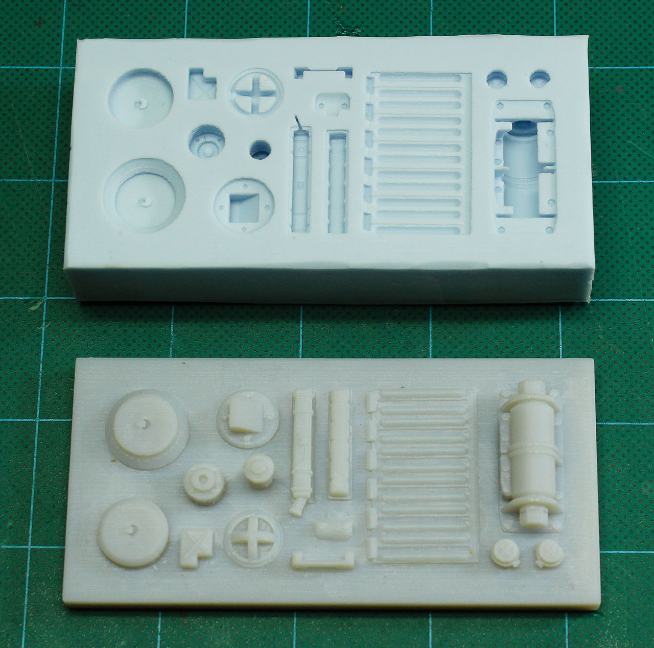
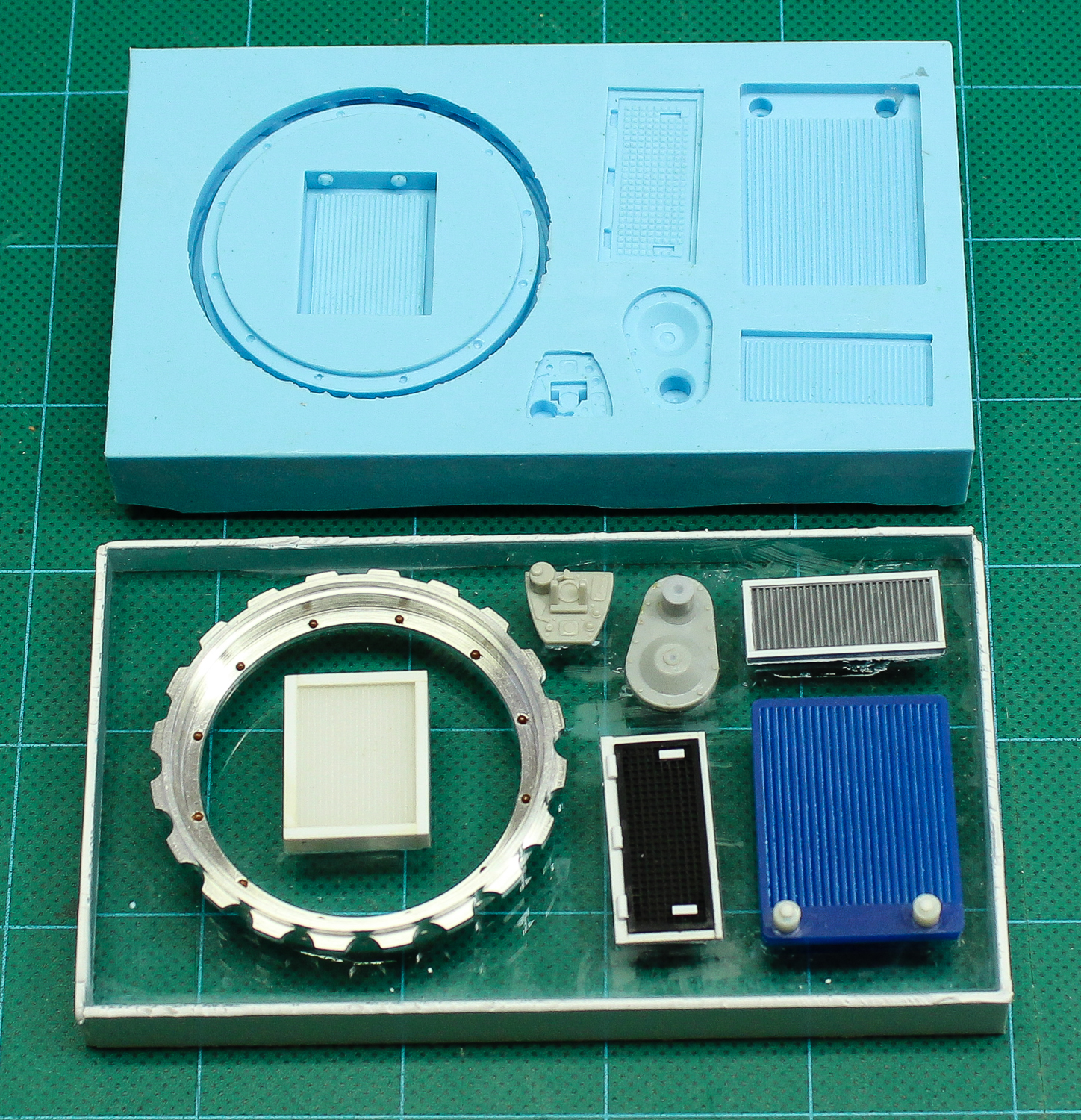
The twin laser canons were comprised of three main components - the barrel (the engine from the Mig kit), a slotted sleeve into which the barrel was inserted and rectilinear base assembled out of laser cut acrylic sheet. I was only able to purchase one of the vintage Mig kits on EBay so it was necessary to make a silicone mold of the engine part and cast the two pieces needed for the model.
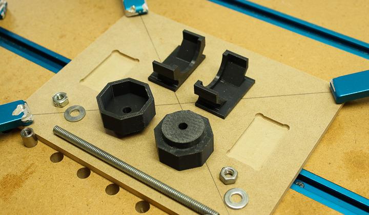
The slotted tube sleeves were cut from plastic tubing available from Plastruct. To cut the eight slots in each tube I leveraged the power and precision of computer modeling, 3D printing and CNC routing. I design a jig fixture comprised of 3D printed octagonal end buttons which fit into the ends of the cut piece of Plastruct tubing and were held in place by a length of threaded rod and a couple of hex nuts.
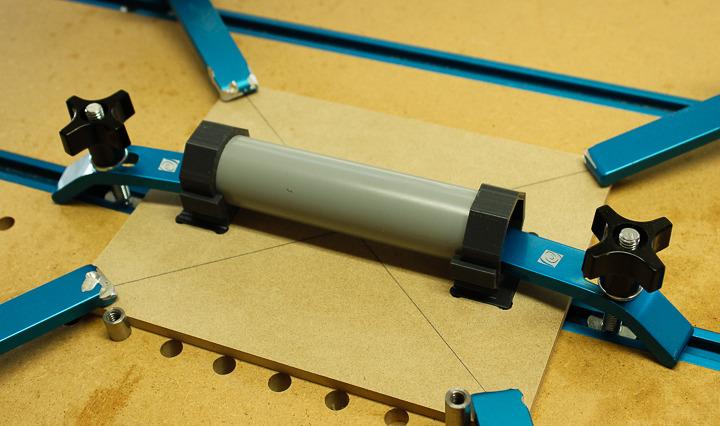
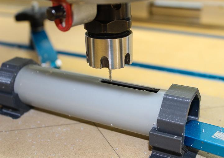
This assembly was then clamped into a set of matching 3D printed cradles which in turn fit into rectangular pockets milled into a MDF base plate on the CNC. Once the tube was securely clamped into the cradles the correctly sized slot could be cut using the CNC router.
Then the tube/button assembly was rotated 45 degrees in the cradles, clamped down and the next slot cut. This was repeated until each tube had been cut with eight identical slots. A little bit of clean up with a square needle file to sharpen up the corners and the sleeves were done.
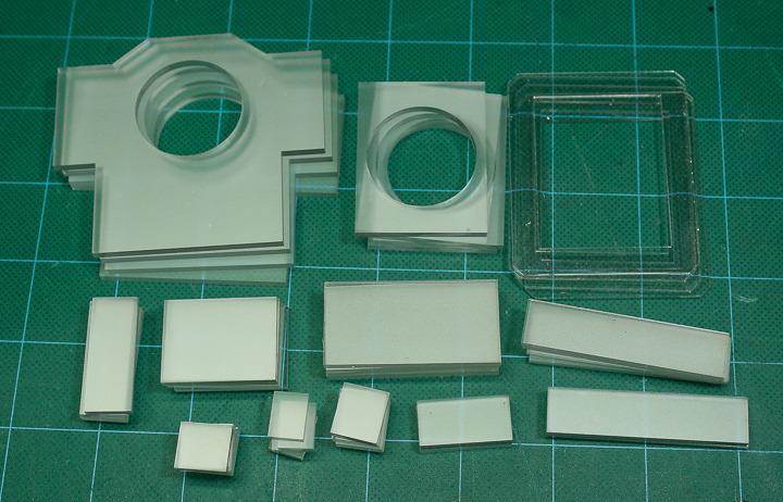
The bases of the laser canons were first 3D modeled in Rhino and then broken down into the component pieces, the same way as was done for the MDF tower casework. In this case the parts were to be laser cut from 1/8" and 1/16" thick acrylic sheet. As with the drawing files for the CNC, the files for the laser cut parts were exported as .dxf files which were then used to run the laser cutter.
The cut parts were glued together with solvent cement. Short pieces of 1/8" square styrene strip we glued into the inside corners of the structures to help re-enforce them.
PART THREE: DETAILING

The original models built for the Star Wars films were detailed with hundreds of little parts taken from plastic model kits. These parts were often referred to as nernies. This was the first time this approach to adding detail for film models had been used to such a great extent and it was one of the defining characteristics of the realistic "used hardware" look of the film. There are photographs of the ILM model shop back in the day showing entire walls stacked high with hundreds of model kit boxes. Models kits of all types and scales were used for "donor parts" but it seems there was a fondness for models of military subjects, especially tanks and other vehicles.
A great deal of time and effort has been spent by members of the Replica Prop Forum (The RPF), Studio Scale Modelers (SSM) and other online sites analyzing photos of the original models and tracking down precisely which parts from which kits were used for the added details. Some of these model kits are still in production and many more are available on EBay, although sometimes at extremely high cost! Other than purchasing the Mig 21 kit to use for the barrels, I decided I didn't want to spend what could amount to many hundreds of dollars purchasing all of the necessary donor kits, some of which are quite rare. Instead I decided to replicate many of the parts with 3D printing, laser cutting and scratch building. In the end, several 'authentic' parts were donated for use on this project by some of the very kind members of the RPF.
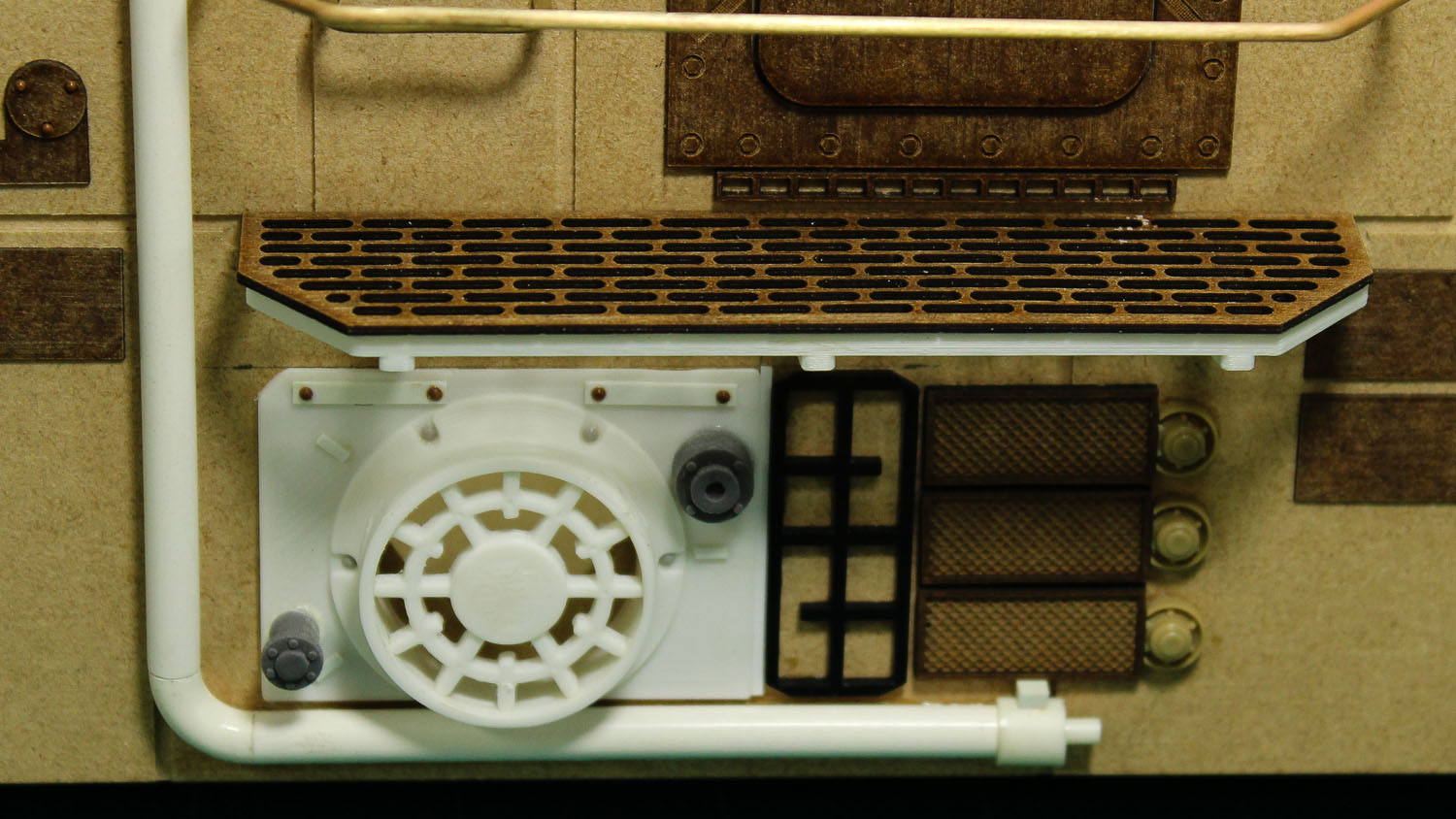
Before applying detail parts some additional layers of plating were needed. Styrene sheet, cut by hand, was used for this plating on the original models but I wanted the benefits of precision and speed that could be achieved using a laser cutter, and styrene doesn't laser cut cleanly, the edges tend to melt a little. Instead I laser cut the plating panels out of a material called Polybak, a cardboard sheeting which has been impregnated with resin to make it water resistant. Polyback is often used to back cabinet panels in moist locations and as a backer for thin wood veneering. It laser cuts beautifully and takes paint well.
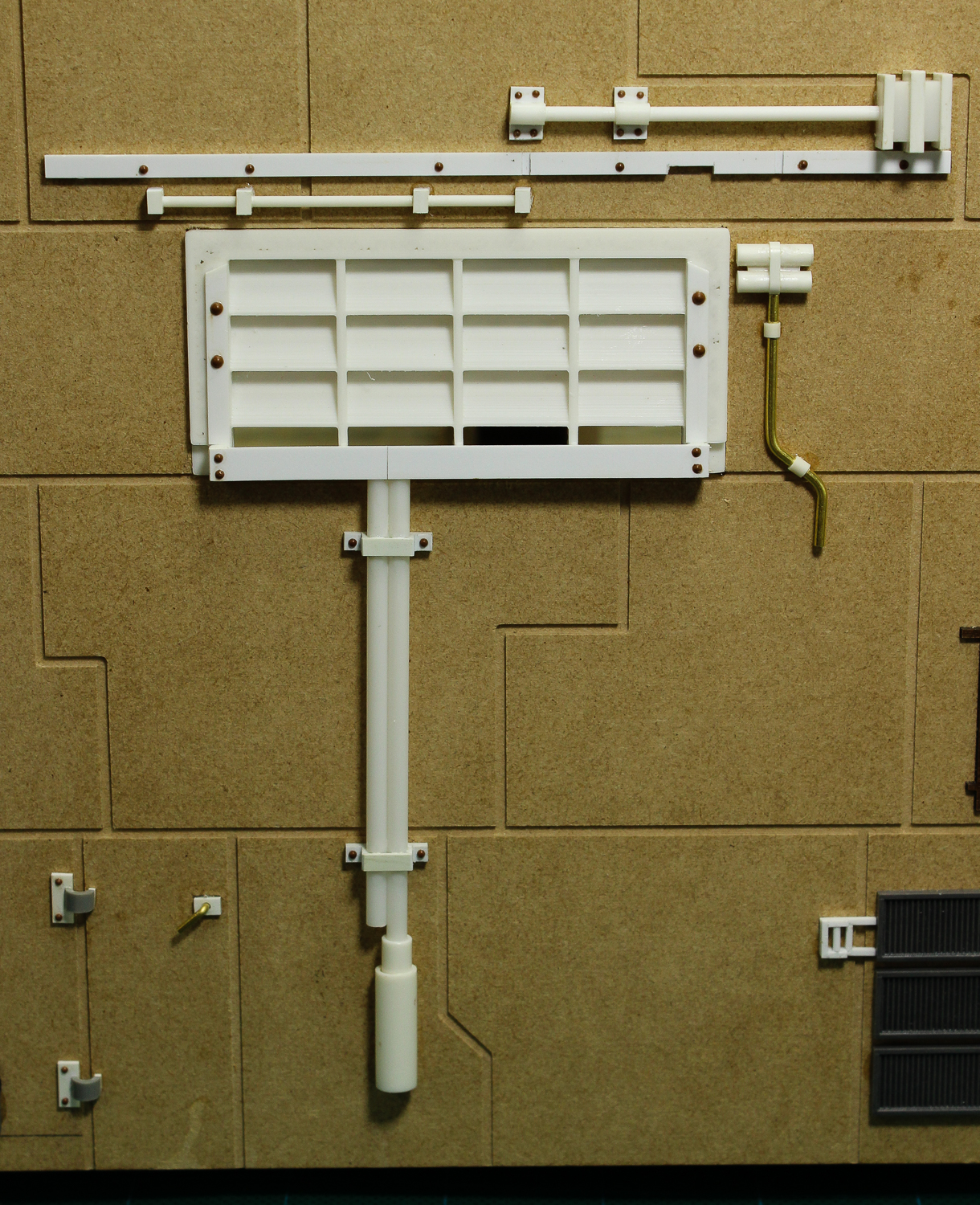
I laser cut a series of panels to go on the top of the tower as well as a bunch of randomly sized rectangular panels that I could stick on the casework wherever desired. Before cutting, I applied double-faced adhesive tape to the back of the Polyback sheet so that to attach the parts all I would have to do was peel off the backing paper and stick the parts down. In additional to the plating, several custom parts were laser cut, some with partial surface etching to represent bolt heads and other details.
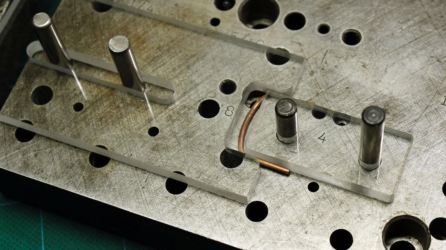
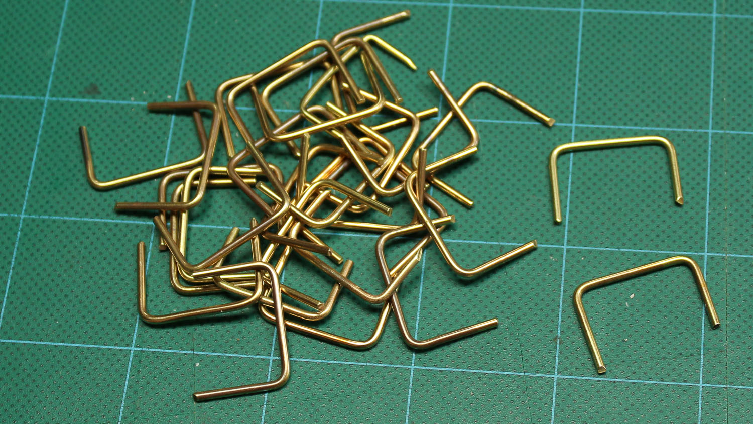
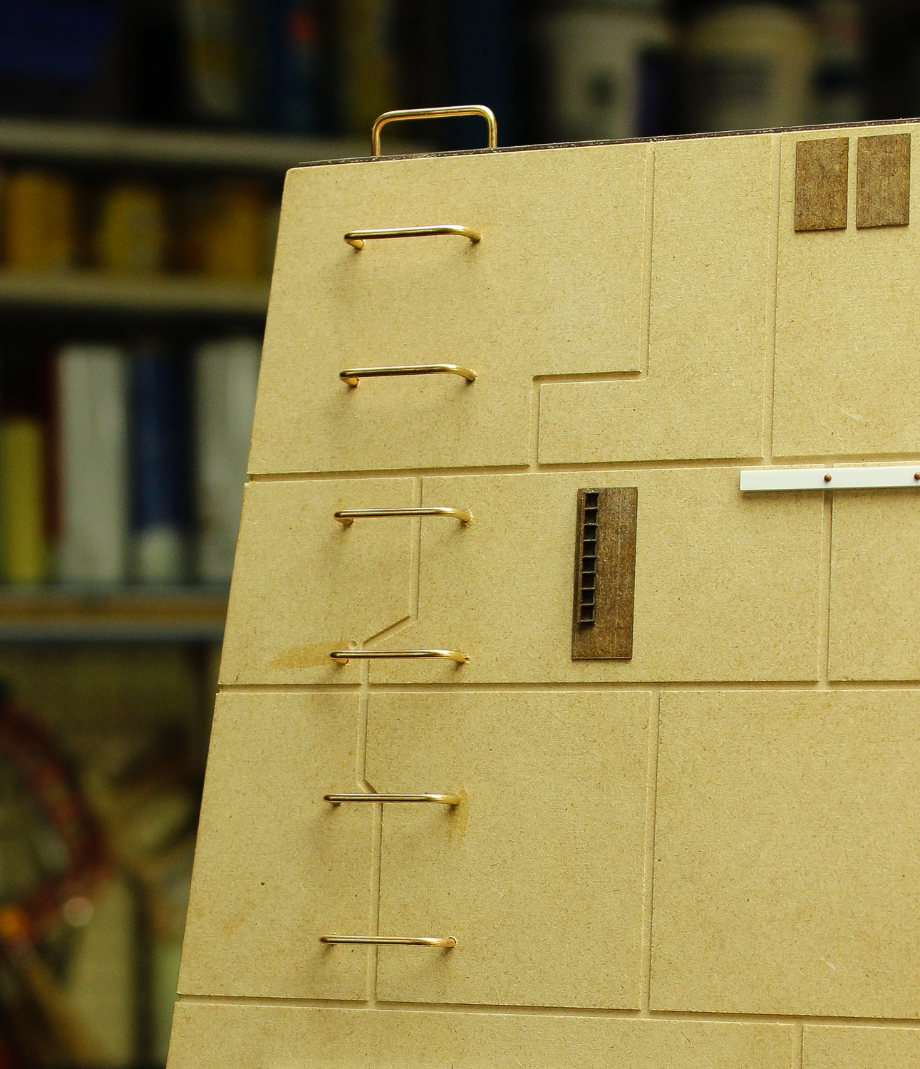
Creating the several dozen bent metal ladder rungs proved to be a unique challenge. The holes for the rungs were precisely drilled into the MDF tower sides as part of the CNC process. To fit these holes, the ladder rungs would all have to be bent to exactly the same width, a very difficult task to do by hand with a pair of round-nose pliers. The solution was to make a bending jig out of acrylic sheet milled to the correct profile with the CNC router and then use these on a jig plate to bend the pieces of brass rod. The acrylic parts were held in alignment on a steel jig plate using dowel pins. The larger piece was able to slide on the pins and the smaller piece was pinned firmly in place. A bar clamp was used to squeeze the two jig plates together with a piece of 1/16 inch brass rod in between. To make the brass rod easier to bend, it was first annealed with a torch.
To bend each rung, an annealed piece of brass rod was placed in the jig between sliding acrylic jaw and the fixed acrylic plate. The bar clamp was used to force the two plates together conforming the brass rod to the desired shape. The finished rungs were then glued in place on the model,
As I had mentioned before, the detail parts on the original model came from (now) vintage plastic model kits. Some of the model makers on the RPF go to great lengths to make sure they have the exact correct part (and only the exact parts) on their models. A process that can take years. I greatly admire that approach, but on the other hand I'd like to get my model built as quickly as possible. As I like to say "Done is my favorite color!" So as I go about detailing the model I'm not really trying to make an exact replica of the filming miniature. I figure it's a BIG Death Star! There are a lot of Laser Towers on it and there are bound to be some differences! Every studio scale replica is in some ways an artistic interpretation of the original and this one is mine.
The task of replicating the kit parts used on the original model was done in several different ways depending on the characteristics of the part. Some of the more complex parts were 3D modeled using Rhino software and then 3D printed. Photos of the filming model and in some cases of the individual model parts themselves were used as reference.
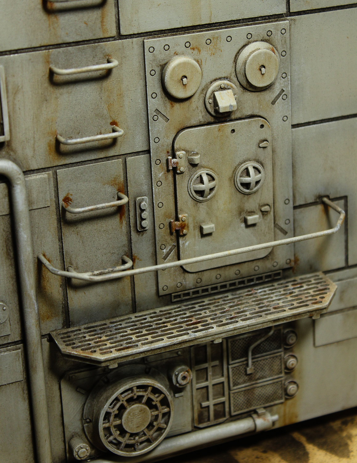
The time had come to start gluing all the various detail parts onto the model. For the most part I used thick super glue to hold the parts in place and a kicker to set the glue instantly.
In addition to the 3D printed, laser cut 3D cast resin parts, some of the details were added the good ol' fashioned way, built up out of styrene strip and rod along with brass wire of various diameters to represent piping.
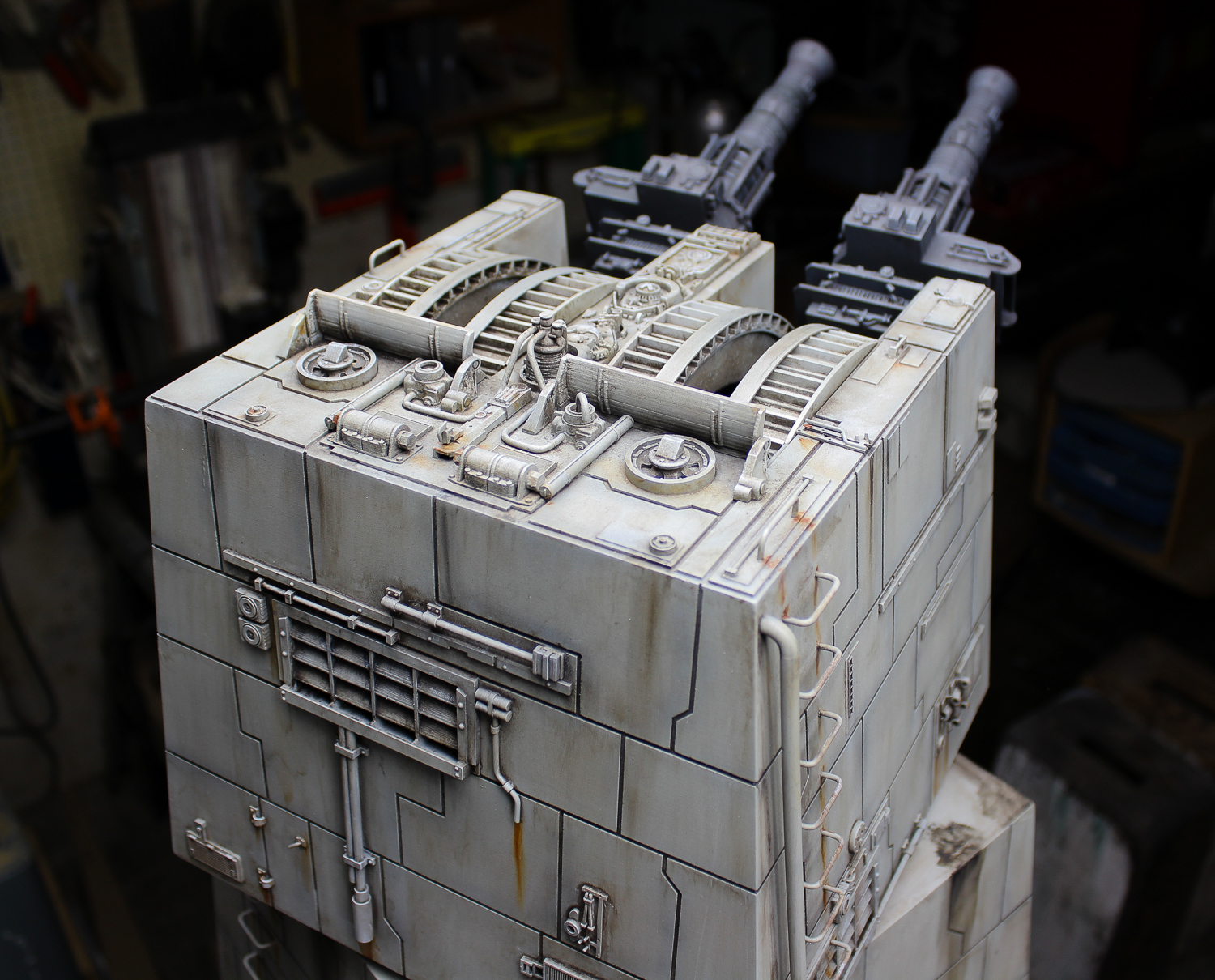
Once all the various detail parts were in place the model was ready to paint. It's fun to see how the original model makers at ILM reused details from other models they were making for the film. The grey detail casting on the top of the turret in between the two barrel slots is known as the "Droid Strip." It's the same detail casting used on the X-Wing Fighter models, on the top of the fuselage just behind the cockpit.

PART FOUR: PAINTING AND WEATHERING
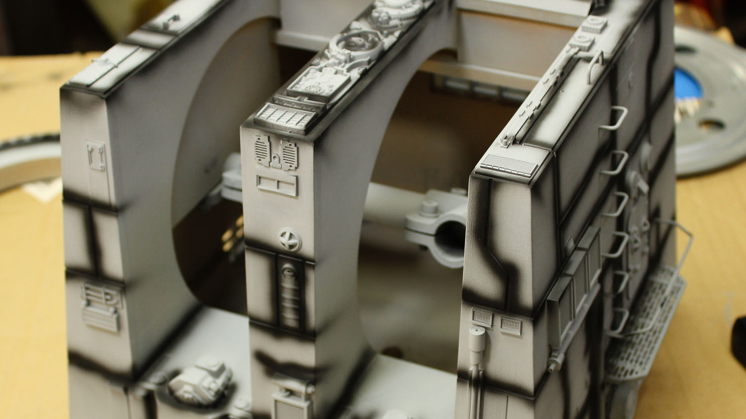
The time has come to paint and weather the model. This is one of my favorite parts of the whole modelmaking process. The time when everything comes together visually as a unified whole. Before painting I disassembled the laser cannons and curved tracks in order to make them easier to paint. The first step is to give the model an overall coat of grey primer. This gives the model a uniform base color, seals the MDF and aids in the adhesion of subsequent paints to the plastic and brass parts. I used a spray can Filler Primer from Rustoleum, applied in several light coats until the model was a uniform shade of grey. It's amazing how just a simple coat of primer can tie everything together!
There was a little bit of over spray (it was a particularly warm weekend) so I went over the whole model with an extra fine scotch bright pad to knock off any dusty overspray. The next step was to "pre-shade" all the panel lines and around some of the detail features with flat black water based Tamiya acrylic paint sprayed with an airbrush. This pre-shading will subtly show through the base paint layer to be applied next giving a little bit of visual depth and variation to the overall look. It's okay that the pre-shading is a little rough and sloppy, it actually looks a little better in the end not being too consistent.
Next was an overall base coat of Tamiya Acrylic Royal Light Grey sprayed on with an airbrush. I thinned the paint almost 1:1 with water and built up the opacity with subsequent coats until I had the amount of pre-shading showing through that I wanted. The thinned paint dries more transparent so it usually takes more coats than you originally think. The end result is a subtle dark shading around the edges of the panels. The effect will be further reduced with the washes and other weathering yet to come.
Next came a little fine overspray of a darker grey applied with an air brush. The overspray doesn't really show up in the pictures but does add a bit of variety to the surface of the model. Once the overspray had dried the whole thing was sealed with a coat of Pledge Liquid Floor Finish, which is basically just a water based clear varnish. This will prevent the wash coming next from staining the base color too much.

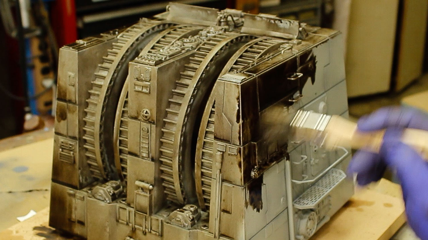
Now it's time to wash up! Only this kind of washing has the opposite effect of cleaning, it makes the model look dirty and weathered.
I love washes; they are simple to apply and do such a great job of bringing out surface detail and texture. I prefer to use oil-based paints on my models as they flow, puddle and dry so nicely. And with oil paints you've got a good bit of time to work them before they dry. Water based paint washes look great when wet but dry quickly tend to be splotchy when dry.
The wash for the laser tower was made from artist's tube oil paints. For this wash I used a mixture of Ivory Black and Burnt Umber to create a brownish black, which is a great overall weathering color for almost anything. The paint was thinned down with odorless mineral spirits but was still fairly concentrated, as washes go. The nice thing about artist's oils is you can apply them really heavy and then wipe most of it off, leaving paint mostly in the corners and recesses.
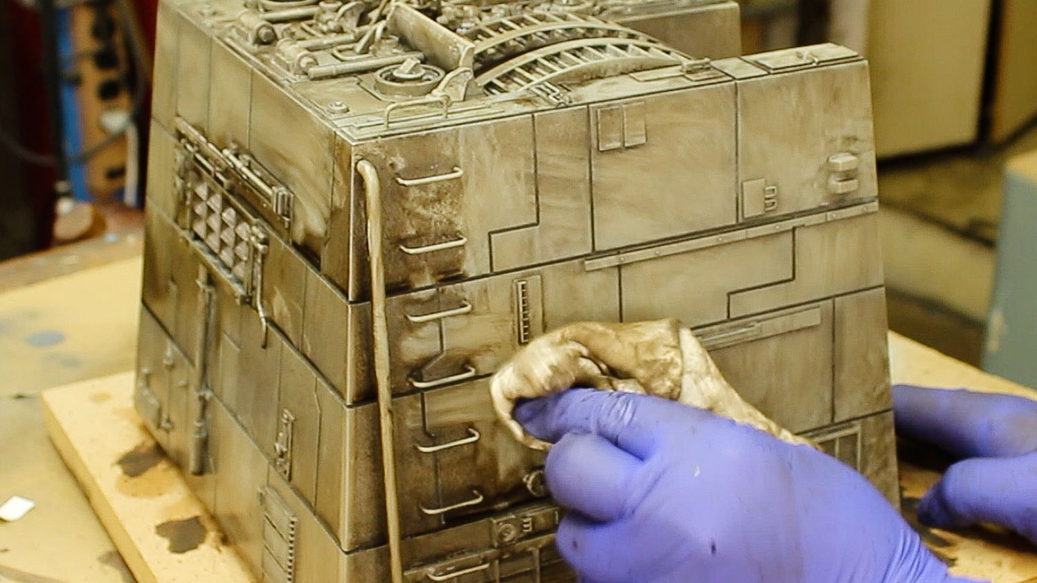
When using oil based washes it's a good idea to pre-moisten the surface of the model with mineral spirits. This helps the wash flow into all the tiny cracks and crevices and keeps it from staining the surface too much. Just apply clean thinner liberally with a big brush before applying the wash. The secret to a good wash is to not be timid, go for it! The wash was applied quite liberally with a big paintbrush, working it into the panel lines and around all the details. Then I wiped off as much of the wash as I could with a clean cotton rag, always wiping vertically from top to bottom to create vertical streaks. It's a messy job but it's amazing to watch all the detail start top pop as the dark wash settles into the cracks!
At this point there is still a lot more wash on the surface of the model then I want, but that's the nice thing about the very long drying time of artist's oils, I can brush more clean thinner over the surface and continue to remove the wash as desired. During this process I also did some specific detailed streaking in places. Though this is really an overall wash and I will be coming back to do more detail spot streaks and washes next. I let this base wash dry for several days so that the thinners used in subsequent weathering would not affect it. There are fast drying artist's oil paints which are handy for detail painting but I prefer the extended working time you get with traditional oils. Besides, who needs to be in such a hurry anyway?!
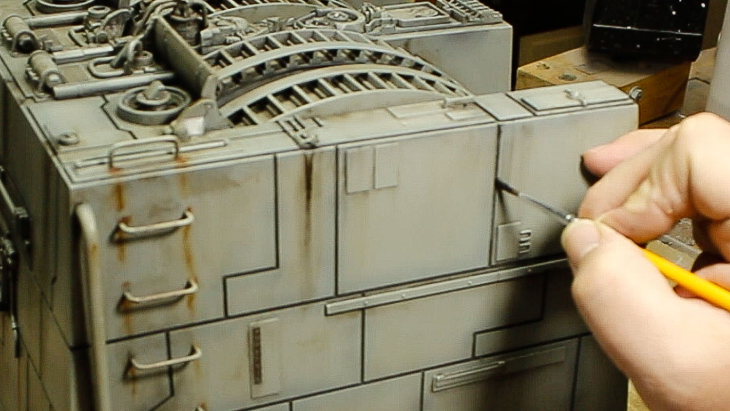
The next step was to add finer detail weathering, mostly streaks and runs, in contrasting colors. As with the washes, I used artist's tube oil paints, but this time straight out of the tube. Color wise, I squirted out dabs of Ivory Black, Titanium White, Raw Umber, Burnt Umber, Raw Siena, Burnt Siena and Dark Rust on a palette and worked back and forth between using each color, both straight, and blended with the others. The Dark Rust (from MIG Productions) turned out to be my favorite. Don't ask me how there's rust in the vacuum of space! That was part of George Lucas' genius; hardware is so worn in space it actually rusts! (and that there's no underwear in space, but that's a topic for another article!). Okay, maybe the Death Star is SO BIG it has its own climate?
As far as technique, it's pretty straight forward. As with the wash, I moistened the area being worked on first with a bit of clean mineral spirits (it's important that the overall wash has dried thoroughly for a couple of days or else this pre-moistening may remove it), then put a little point of paint at the top of where I wanted the streak to be and worked it down with a clean brush or rag. Since the oils take a couple days to dry there's plenty of time to play around with it, or even remove some weathering entirely with thinner if you don't like how it's going. Once I was happy with the look of the streaks I set the model aside again to dry before moving onto the next step, dry brushing.
Dry brushing is exactly what it sounds like. A paintbrush with very little paint on it, almost "dry", is lightly brushed over edges of the model depositing minute amounts of paint. Usually dry bushing is done with very light shade of paint which adds visual highlights to the model. Dry brushing can also be used to make a model look dusty, add the effect of old rust or just add a subtle texture to a flat surface.
For this model I used a very light grey for the dry brushing to add highlights to the top edges of the various details. As with the washes, I used artist's tube oil paints, again since they take a long time to dry and won't dry out in the brush as acrylics or enamels might.
The technique for dry brushing is very simple, I put a small dab of the light grey oil paint on a scrap of cardboard and then dipped a narrow flat brush into it. Then I wiped the brush against a paper towel to get out as much paint as possible. Then very lightly ran the brush over the edges of the model leaving very small traces of paint behind. As I was trying to simulate highlights I concentrated the dry brushing on the upper edges of the details. When dry brushing it is not necessary or desirable to pre-moisten the surface with paint thinner. Although, as with the washes, if some of the dry brushing doesn't look like it should it's easy to remove it with a little paint thinner on a rag or cotton swab. Dry brushing is a subtle effect, but it adds a lot to the overall impression of the model.

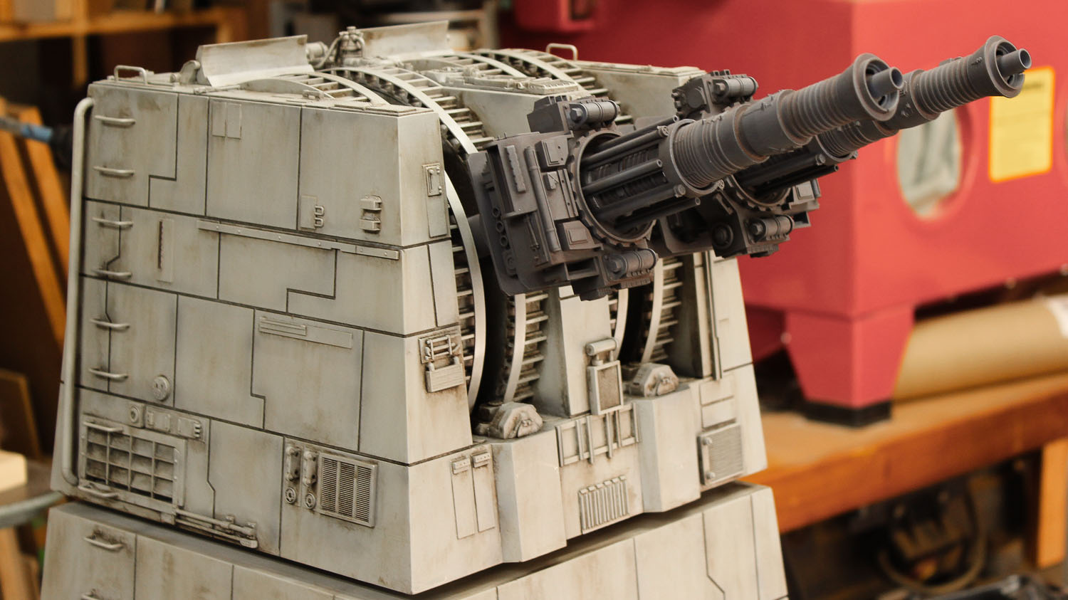
The painting process on the laser canons was similar to the rest of the model but with a different color palette. Using an airbrush, I sprayed the parts with a dark bluish grey acrylic base coat to give the canons a cool undertone. Over that I airbrushed a selective overspray of a Dark grey. The parts were then sealed with Pledge floor polish and once that had dried given a wash. This time I used an enamel wash made from Testors Rubber Black oil based enamel. Rubber Black is one of my favorite wash colors.
Once the wash had dried I applied a selective overspray of Tamiya Acrylic NATO Black and Gun Metal to give it a little metallic kick. Following an application of satin clear varnish to seal the surface I applied an oil-based blackish 'pin wash' just to the nooks and crannies to add a little more shadow effect.
As with the rest of the model I dry brushed the laser canons with a light grey oil paint to bring out the highlights.

At last it was time for the final assembly! 3D printed parts were used inside the turret to connect the laser canons to a horizontal pivot. While the canons aren't motorized they can be positioned at different angles for display.
It's important to sign and date one's work! In this case with a little laser engraved plate.
The finished model! I just love how this one turned out. An iconic model from one of the greatest movies of all time. Come on you Rebel scum, take your best shot!